Assignment
- Use a sensor from the JVC kit or borrowed components to measure a physical quantity using Arduino.
- Calibrate the sensor (in a chart or table show how the measured value relates to the indicated value).
- Include a circuit diagram and source code (IDF: code snippets) on your website.
- Bonus: Build your own capacitive sensor using a piece of conductive material and calibrate it.
- For inspiration, check the Arduino Projects Book.
Sensor
For this assignment, I decided to use an NTC thermistor that I had left over from my old Original Prusa MK3 which I upgraded to an MK3.5 late last year.
NTC Thermistor
NTC thermistors are resistors with a negative temperature coefficient, which means that their resistance decreases with increasing temperature. This makes them ideal for measuring temperature.
Usually, NTC thermistors are used in 3D printers to measure the temperature of the hotend and the heated bed. The heatbed thermistor is a glass bead thermistor, which is a type of NTC thermistor that is encapsulated in a glass bead. This type of thermistor is very accurate and has a fast response time.
Thermistor information
For this assignment, I used a thermistor with the following specifications:
- Resistance at 25°C: 100 kΩ
- Beta value: 4092*
- Operating temperature: -40°C to 300°C
*sourced from MK3S configuration in Prusa FW (based on Marlin)
Calibration
Method
I measured 3 different temperatures with the thermistor as well as a control thermometer that I found (a meat thermometer, I didnt have anything else with the same temp range). I stuck both together with aluminum foil so that the temperature difference between the two would be minimal and always left them in the conditions for a long enough time for the temperature to stabilise. 5 minutes at least. I took 5 measurements, restarting the thermometer every time, which also stirred around the liquid it was submerged in for example. Wrote down the resistance of the NTC as well as the temperature. I used a Metex M-3800 digital multimeter.
Measuring conditions
- Ice water
- Room temperature
- Hot water (around 70 degrees)


Measurements
| Temperature (°C) | Resistance (Ω) |
|---|---|
| 1.43 | 306 400 |
| 20.43 | 121 560 |
| 68.26 | 17 436 |
How do you temperature?
For thermistors, there are two common methods of calculating the temperature from the resistance:
Steinhart-Hart
As I already have the Beta value from the Marlin firmware documentation, I decided to try the Steinhart-Hart equation first. The Steinhart-Hart equation is a third-order polynomial equation that relates the resistance of the thermistor to the temperature. The equation is as follows:
Where:
- T is the temperature in Kelvin
- R is the resistance in ohms
- A, B, and C are the Steinhart-Hart coefficients
To calculate the coefficients, I used the following equations:
- A = 1/T1 - B * ln(R1) - C * ln(R1)^3
- B = (1/T2 - A - C * ln(R2)^3) / ln(R2)
- C = (1/T3 - A - B * ln(R3)) / ln(R3)^3
Where:
- T1, T2, and T3 are the temperatures in Kelvin
- R1, R2, and R3 are the resistances in ohms corresponding to the temperatures
I came across this cool applet that did the calcualtion for me, as I am lazy.
After entering the values, I got the following coefficients:
- A = 0.006608622952
- B = 0.002266935852
- C = 0.00000005819722188
Beta parameter
For the Beta parameter equation, the equation is as follows:
Where:
- T is the temperature in Kelvin
- T0 is the reference temperature in Kelvin (usually 25°C)
- R is the resistance in ohms
- R0 is the resistance at T0 in ohms
- B is the Beta value of the thermistor
The applet automatically calculated this too. These are the values I got:
- Beta = 3959
- Resistance at 25 degrees Celsius = 98kΩ
Which is very close to the values I had from the Marlin firmware documentation. Good way to check its not complete bullshit. Great!

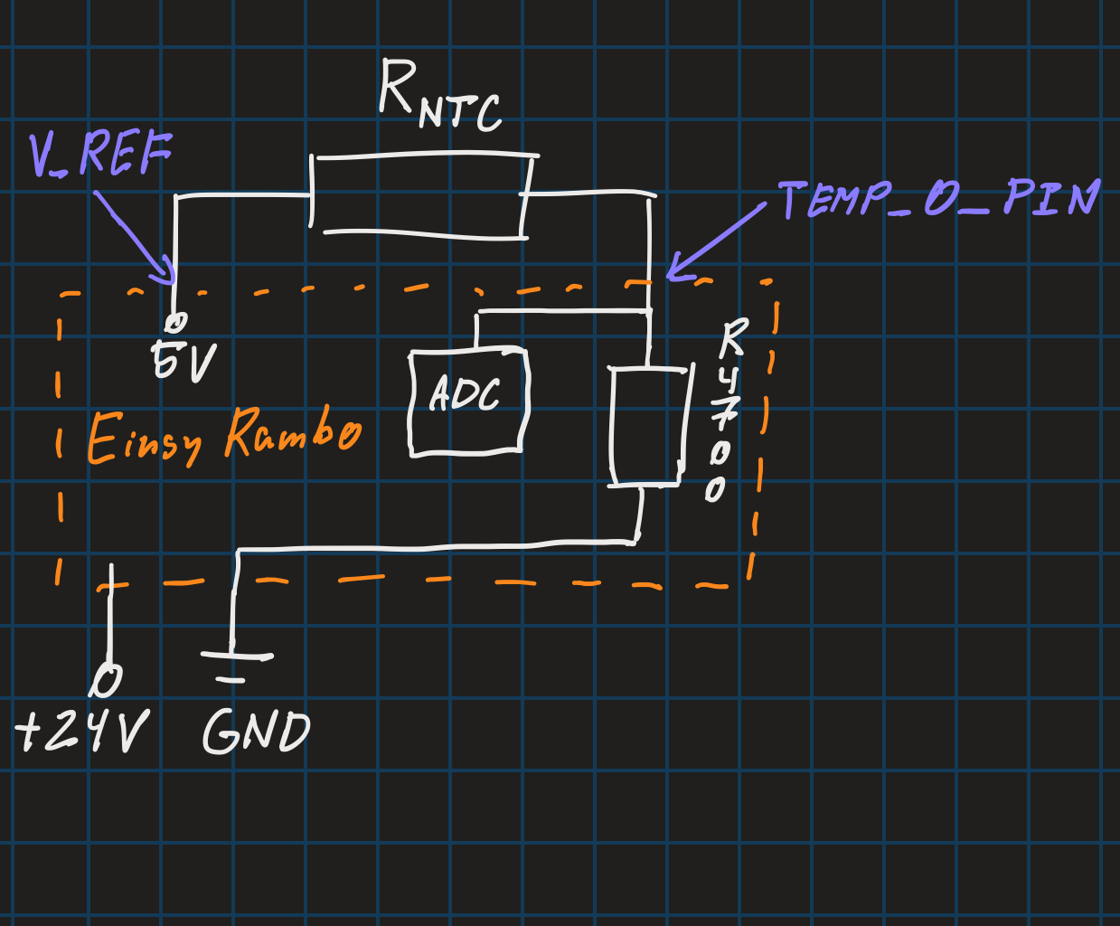
Circuit diagram
The usual way to measure the resistance of a thermistor is to use a voltage divider. The voltage divider consists of two resistors in series, one of which is the thermistor the other is a pull-up resistor with a known value. The voltage across the thermistor is measured and used to calculate the resistance.
In the case of me using an Einsy Rambo, the appropriate pin is already set up as an analog input. The pull-up resistor is already built into the board, so I just need to connect the thermistor into one of the 3 temperature slots

Source code
The source code is very simple. I used the analogRead function to read the voltage across the thermistor and then used the Steinhart-Hart equation to calculate the temperature. The code is as follows:
// Thermistor readout to serial code:
#include "pins_EINSY_RAMBO.h" // Include the pin definitions for the Einsy Rambo board, sourced from the Marlin firmware

// For a 100k NTC thermistor with 4.7k pull-up resistor:
const float CELSIUS_TO_KELVIN = 273.15; // Absolute zero in Celsius
const float PULLUP_RES = 4700; // the value of the resistor in series with the thermistor (usually 4.7k)
const float V_REF = 5.0; // Reference voltage for the ADC (usually 5V)

// For Beta thermistor calculations from Marlin:
const float MARLIN_NOMINAL_RES = 100000; // Resistance at 25 degrees C
const float MARLIN_NOMINAL_TEMP_C = 25; // Nominal temperature in Celsius
const float MARLIN_BETA_K = 4092; // The beta coefficient of the thermistor from Marlin

// For Beta thermistor calculation using my own values:
const float NOMINAL_RES = 98000; // Resistance at 25 degrees C
const float NOMINAL_TEMP_C = 25; // Nominal temperature in Celsius
const float BETA_K = 3950; // The beta coefficient of the thermistor

// For Steinhart-Hart calculations:
const float A = 0.0006608622952; // Coefficient A for Steinhart-Hart equation
const float B = 0.0002266935852; // Coefficient B for Steinhart-Hart equation
const float C = 0.00000005819722188; // Coefficient C for Steinhart-Hart equation

void setup()
{
Serial.begin(115200); // Start the serial communication at 115200 baud rate
Serial.println("Thermistor Test");
pinMode(TEMP_0_PIN, INPUT); // Set the thermistor pin as input
}

void loop()
{
// Read the thermistor value from the analog pin
int voltage = analogRead(TEMP_0_PIN); // Read the voltage from the thermistor
float measuredVoltage = voltage * V_REF / 1023.0; // Convert ADC reading to actual voltage
float resistance = (PULLUP_RES * measuredVoltage) / (V_REF - measuredVoltage); // Calculate the resistance of the
thermistor

// Calculate the temperature using the Steinhart-Hart equation
float steinhart = 1.0 / (A +
B * log(resistance) +
C * pow(log(resistance), 3));
steinhart -= CELSIUS_TO_KELVIN; // Convert to Celsius
Serial.print("Temperature from SH-H (C): ");
Serial.println(steinhart);

// Calculate the temperature using the Beta equations
float tempK = 1.0 / (1.0 / (NOMINAL_TEMP_C + CELSIUS_TO_KELVIN) +
(1.0 / BETA_K) * log(resistance / NOMINAL_RES));
tempK -= CELSIUS_TO_KELVIN; // Convert to Celsius
Serial.print("Temperature from Beta (C): ");
Serial.println(tempK);

// Calculate the temperature using the Marlin beta equations
float tempKMarlin = 1.0 / (1.0 / (MARLIN_NOMINAL_TEMP_C + CELSIUS_TO_KELVIN) +
(1.0 / MARLIN_BETA_K) * log(resistance / MARLIN_NOMINAL_RES));
tempKMarlin -= CELSIUS_TO_KELVIN; // Convert to Celsius
Serial.print("Temperature from Marlin Beta (C): ");
Serial.println(tempKMarlin);

delay(1000);
}
You can also download the code from the links below, or view it on GitLab. I have included the pin definitions for the Einsy Rambo board in a separate file. The pin definitions are sourced from the Marlin firmware, so they should be correct. I just made file be able to work on its own, so I just deleted conditionals that were used in conjunction with other files and safety checks (like if the board is Einsy Rambo or not).
Test
I tested the code on my Einsy Rambo board and it worked perfectly. I was able to read the temperature from the thermistor and display it on the serial monitor. I also compared the readings with the control beta value sourced from Prusa firmware and they were very close.


As you can see, the readings are very close to the control thermometer. The difference is around 0.5 degree Celsius, which is acceptable for my purposes.
Conclusion
I learned a lot about thermistors and how to use them with Arduino. I also learned how to calibrate them and how to calculate the temperature from the resistance. I also learned how to use the Steinhart-Hart equation and the Beta parameter equation to calculate the temperature. I am very happy with the results.
Most of the time was taken up by studying documentation for the Rambo board. I will probably make a tutorial on how to set that stuff up on a separate page.