Week 4
Soldering and designing circuits in KiCAD
Assignment
-
Create an electronic circuit that does something (at least blink).
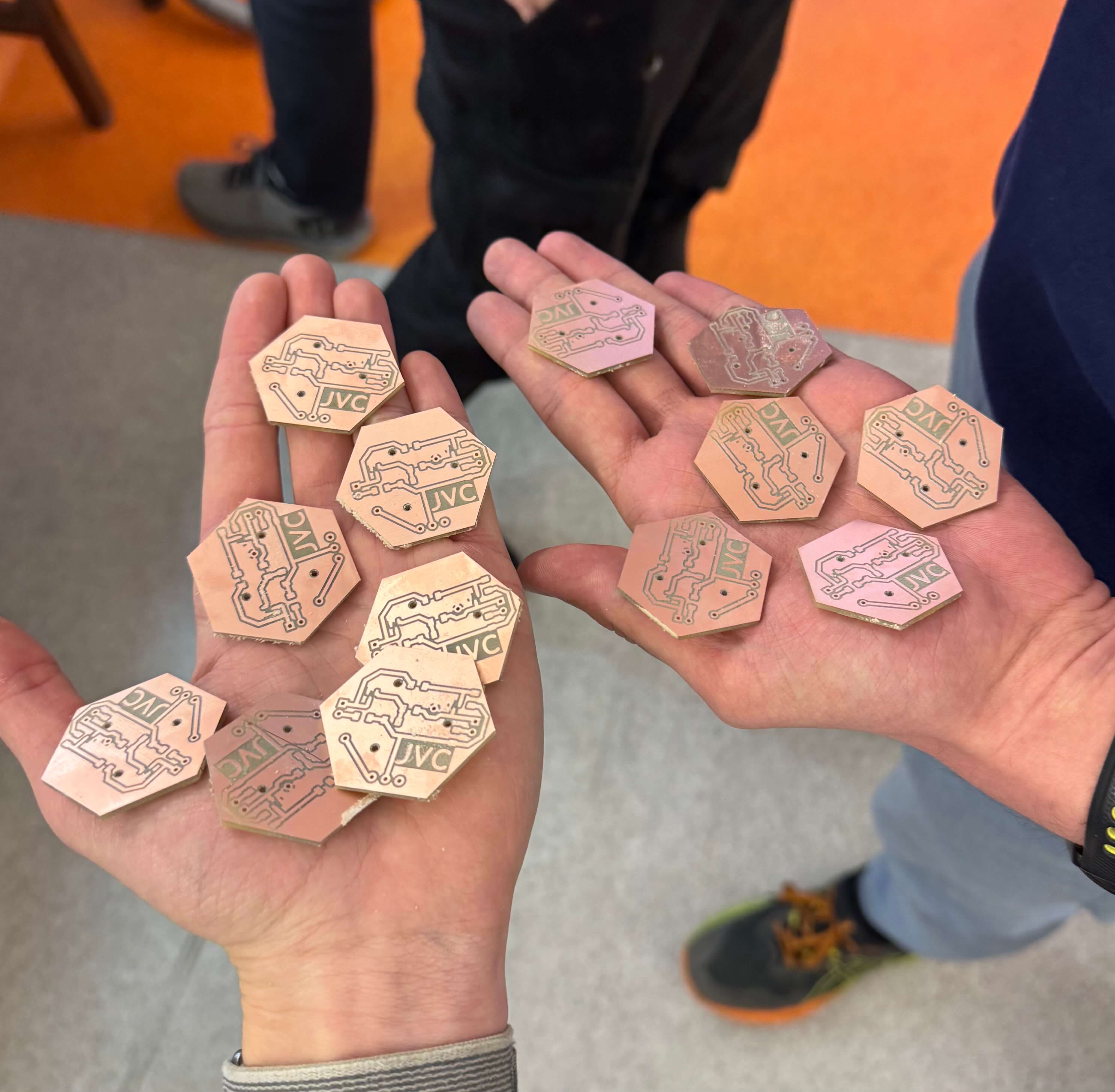
Do not use a breadboard for connections.- Option 1: Populate (or mill) a simple blinker circuit on a PCB.
- Option 2: Build a blinker from discrete components on a universal PCB or as a freeform circuit.
- Option 3: Build a blinker with Arduino (we’ll cover Arduino more next week; you can refer to the Arduino Projects Book). Mount the Arduino in headers so it can be removed.
- On your website, document the schematic of the circuit.
Designing a circuit
I attempted to design a circuit in KiCAD for WS2812B NeoPixel LEDs. The idea was to form a bow tie powered by an Arduino Nano, running cables from a power bank in a pocket. However, managing four wires for each of six LEDs with different wire thicknesses was more challenging than anticipated. The thicker copper backbone required higher heat for soldering, causing issues when attaching thinner wires.

Soldering
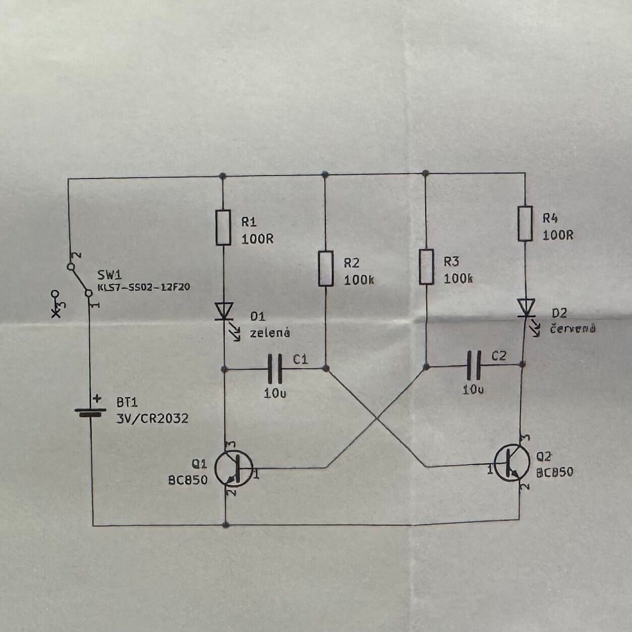
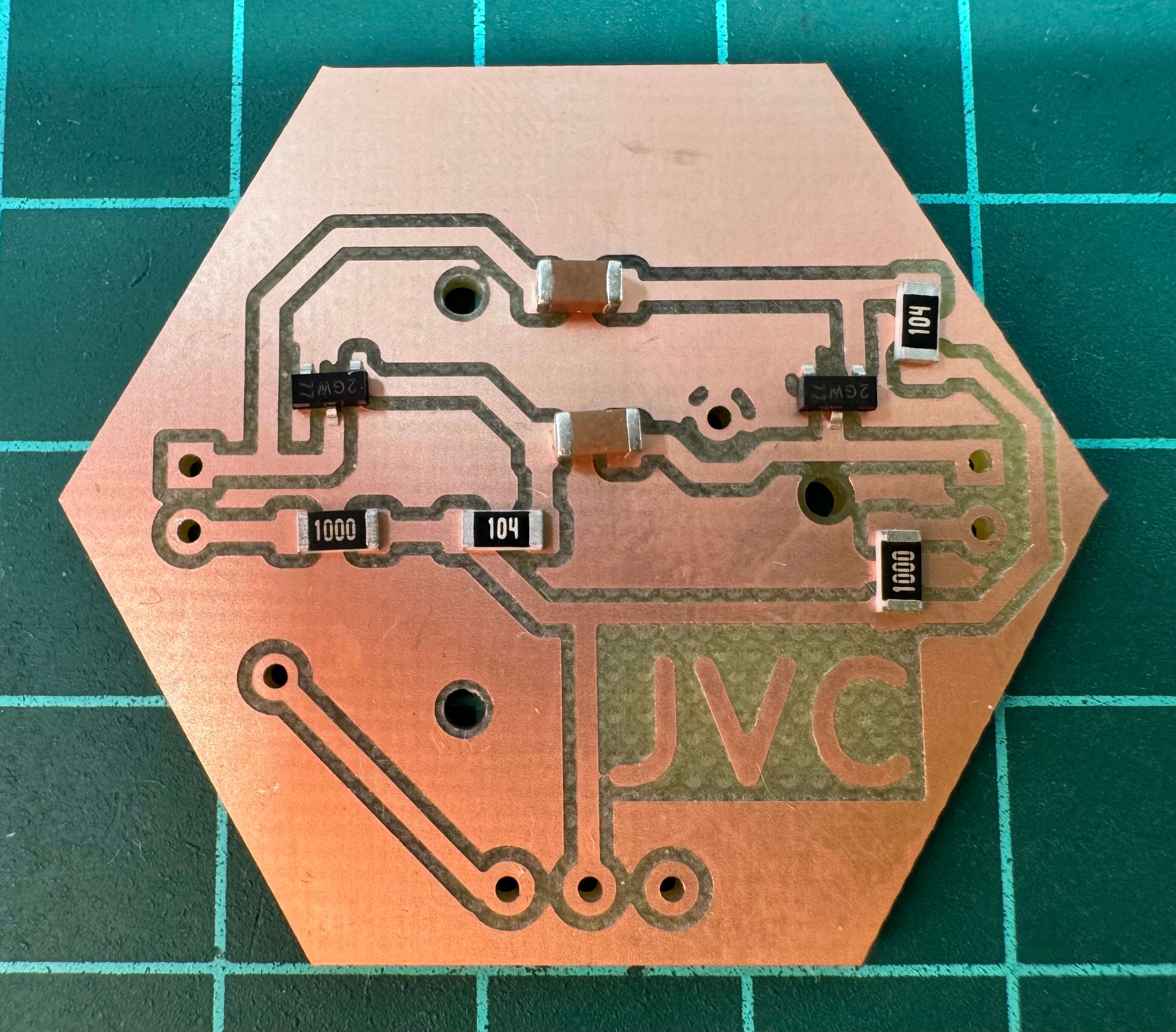
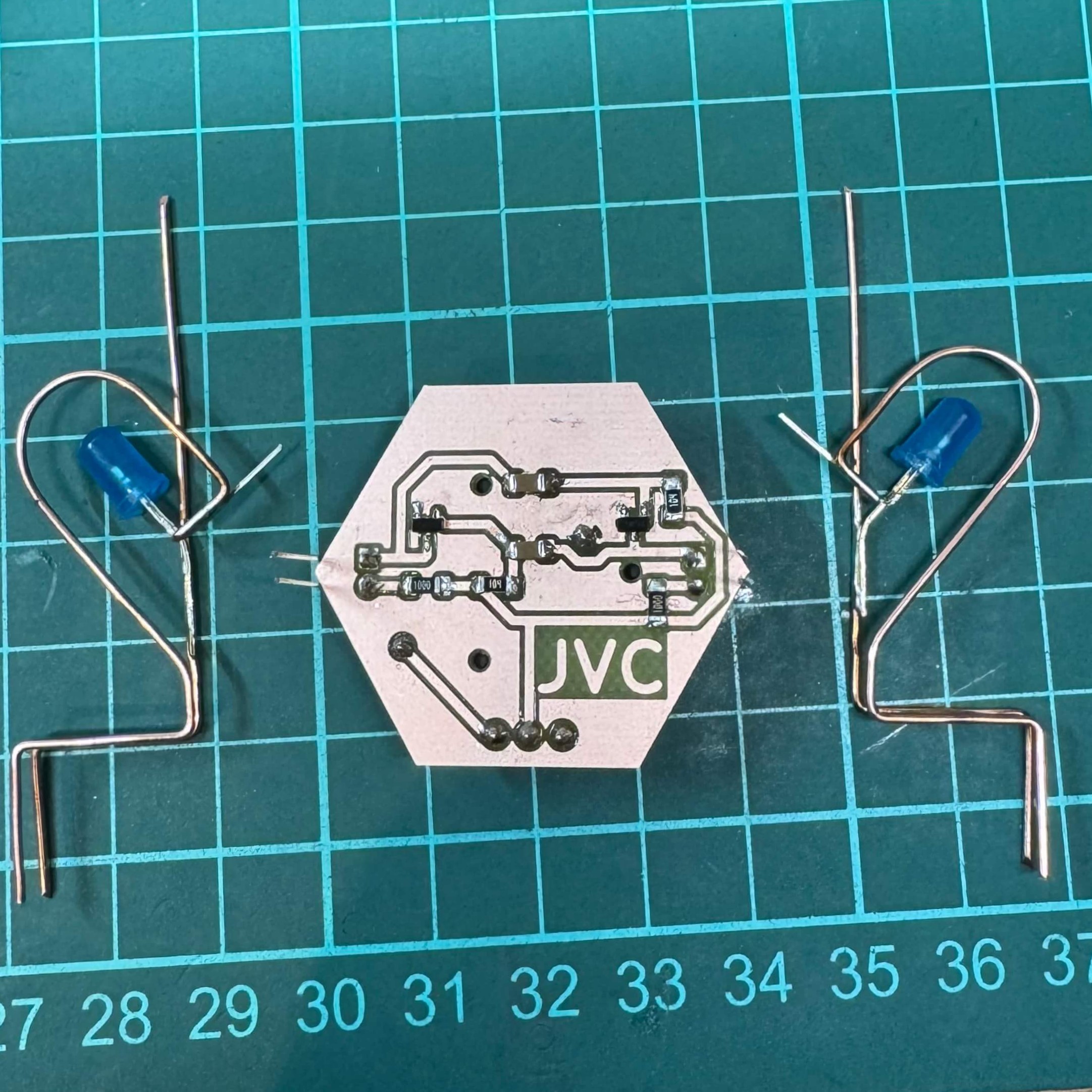
Since my experimentation withv freeform didnt work out as planned, I decided to solder the JVC hexagon with an oscillating circuit that will make two LEDs. I used the following components:
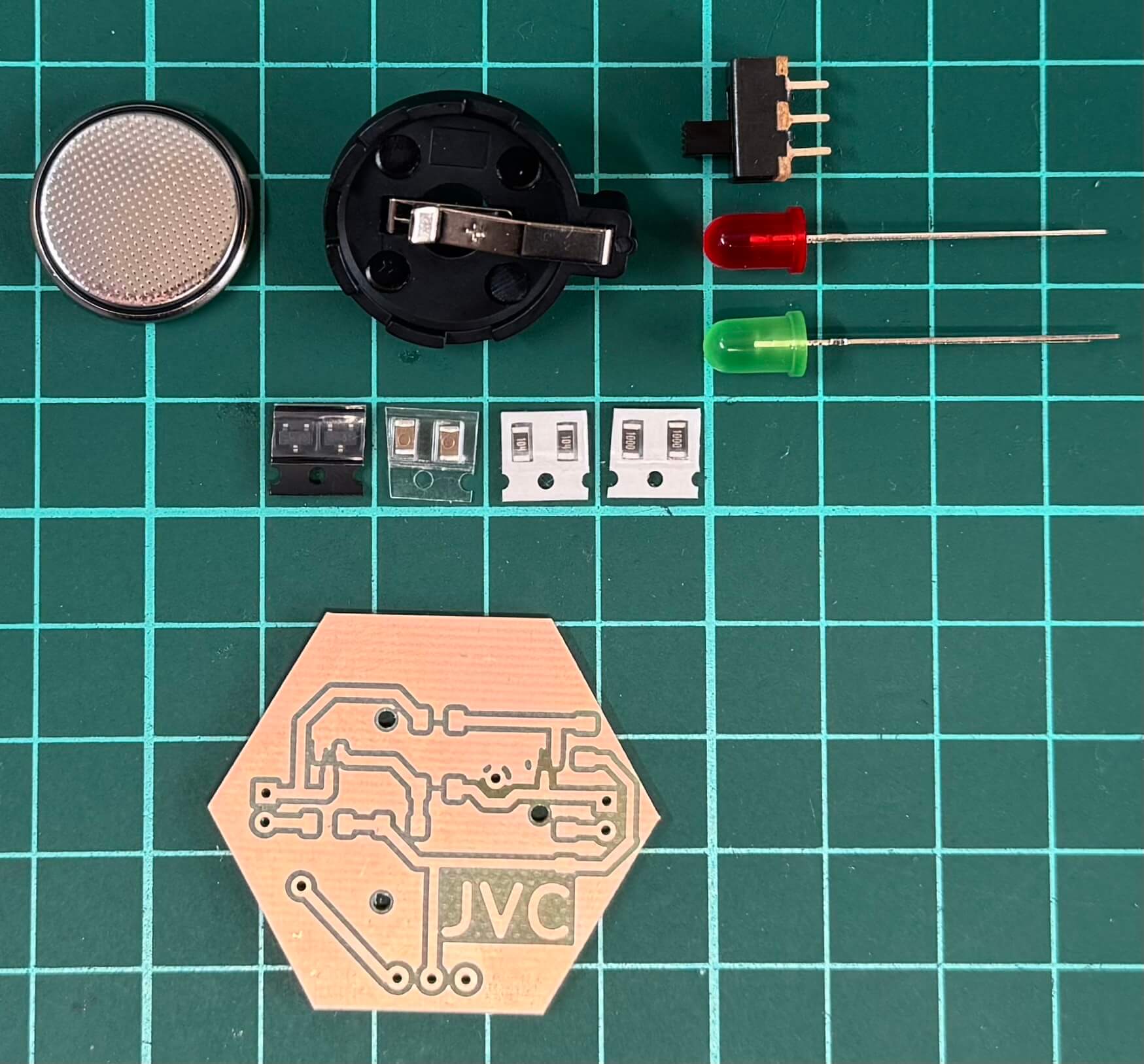
- SMD: 100 Ω resistors, 2× 10µF capacitors, 2× 100k Ω resistors, 2× BC850 transistors
- THT: 3-pin on/off switch, 2× LEDs (any color), CR2032 battery holder + battery
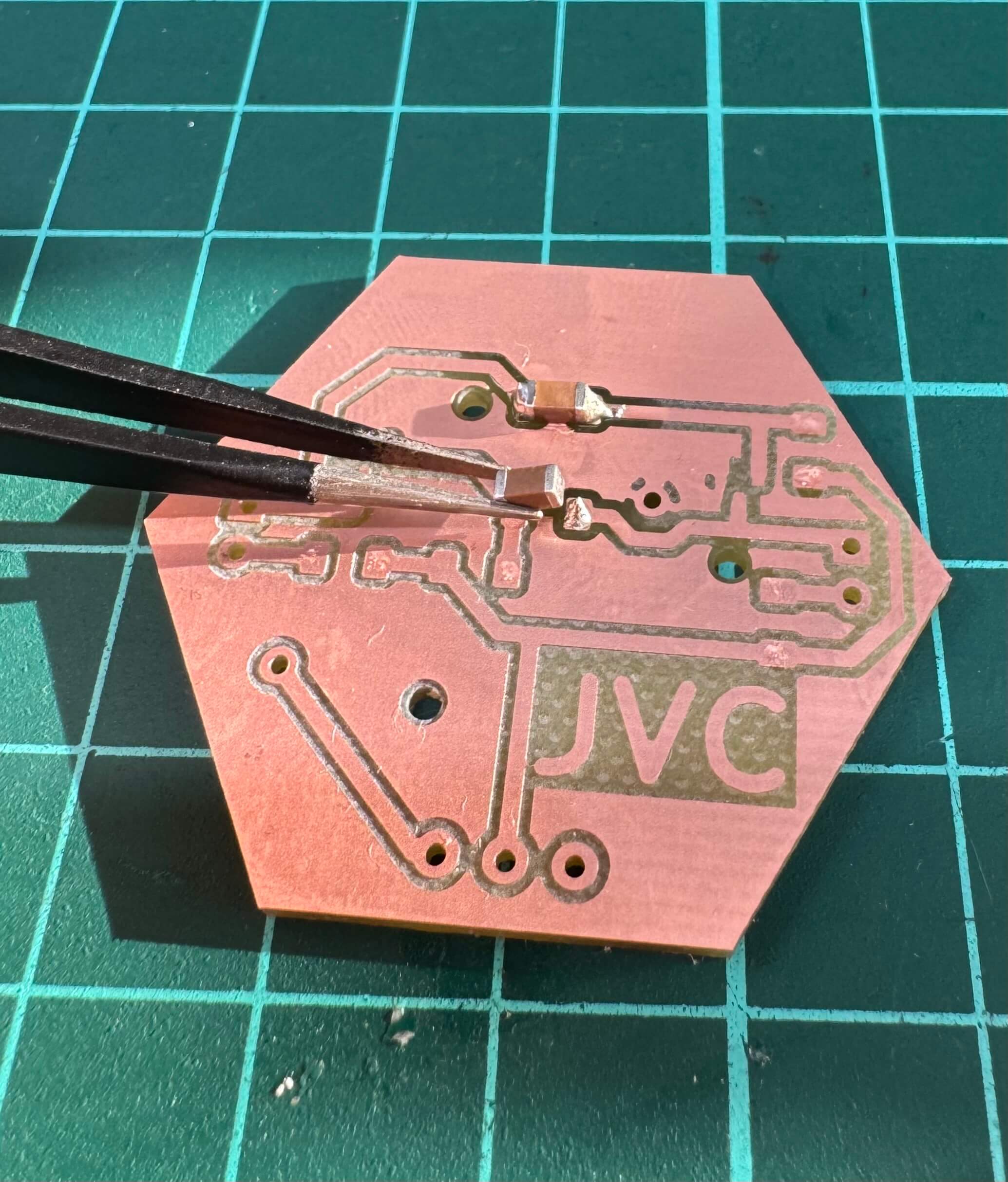
SMD Soldering
The technique for SMD components:
- Add a bit of solder to one contact.
- Place the component onto that solder spot, then fix the other contact normally.
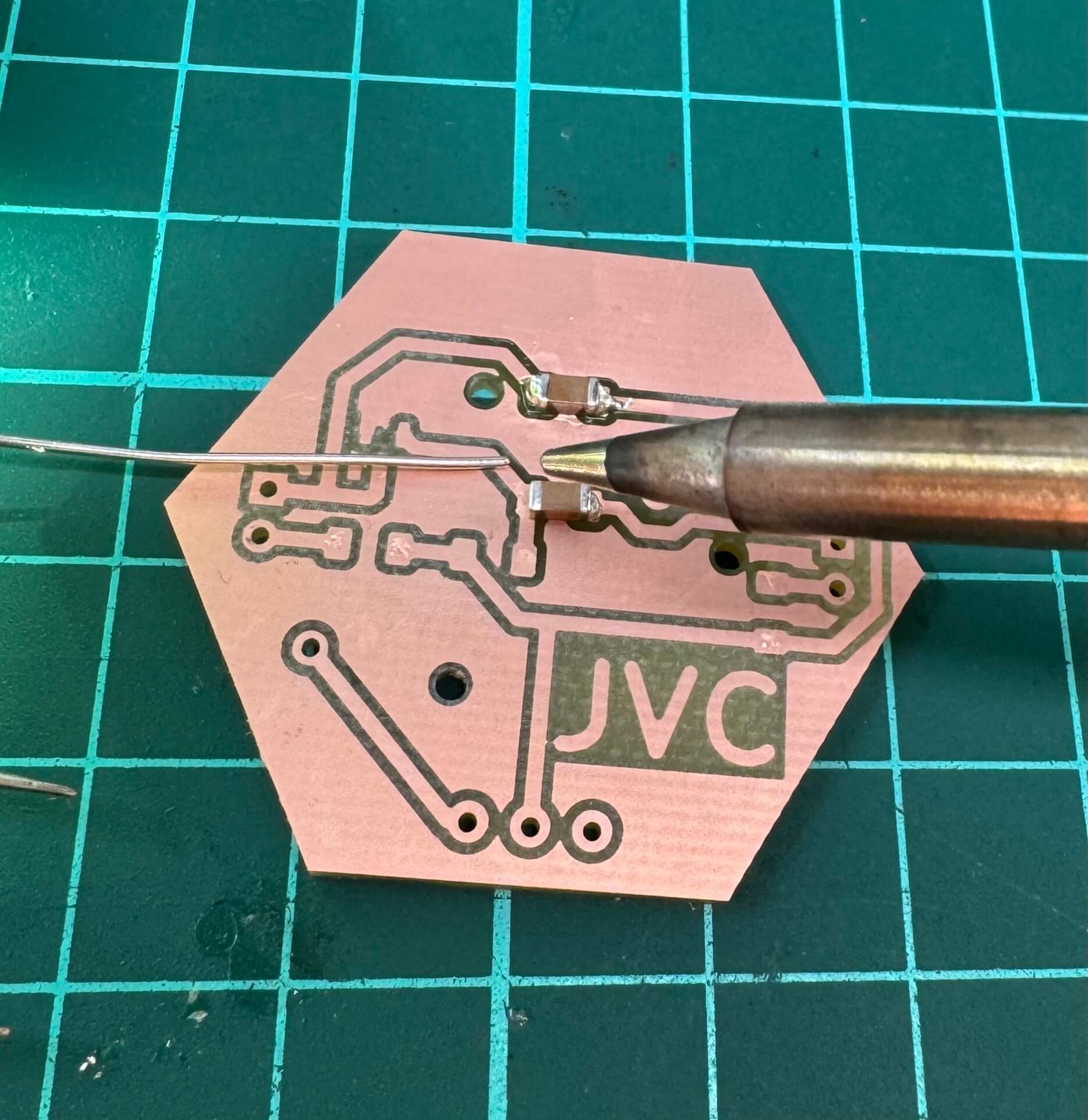
THT Soldering
- Insert the THT component from the opposite side of the solder pad.
- Solder one lead, then the other, and trim any excess.
Pro Tip
Always use flux to get professional-looking joints.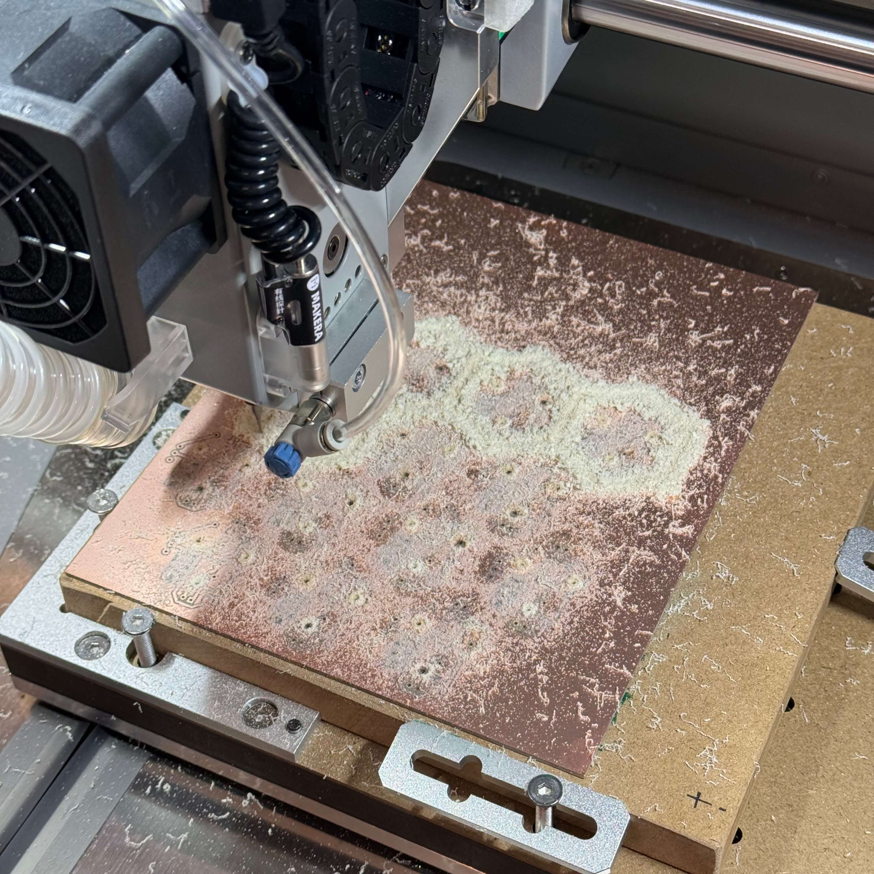

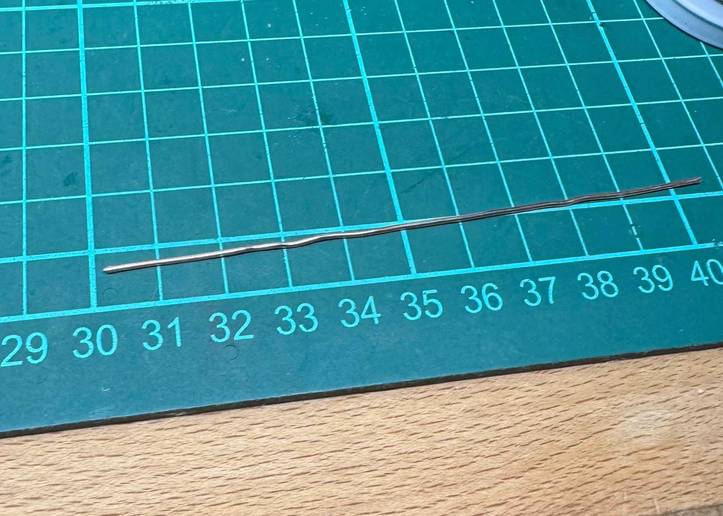
Freeform Soldering
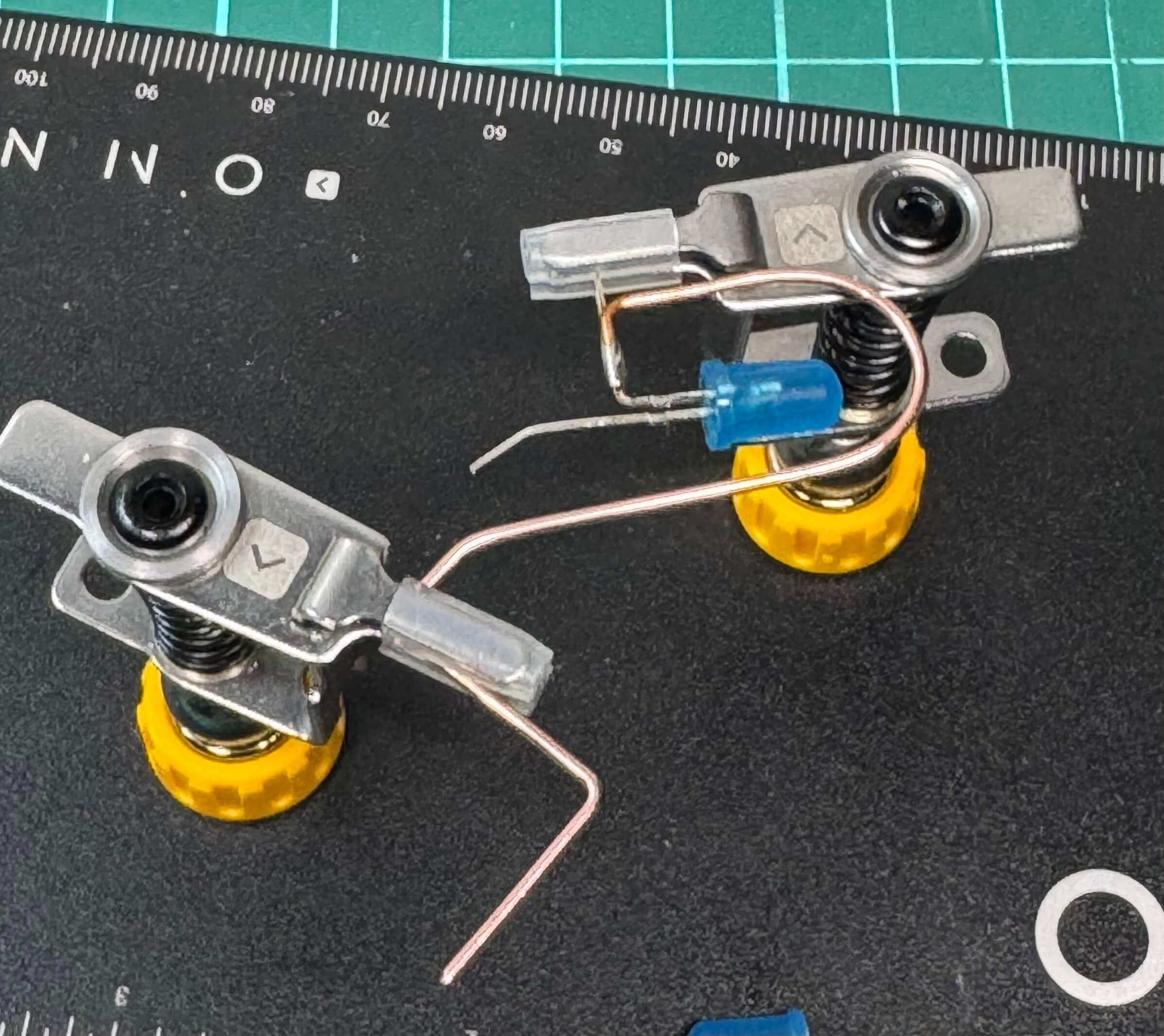
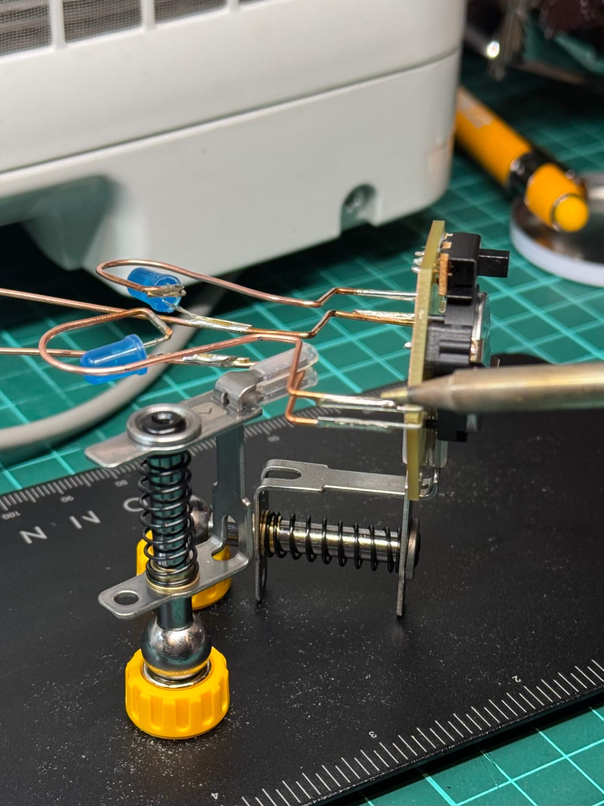
When I had the JVC hexagon working, I decided to try freeform soldering, my second attempt at it. This idea came to my mind when I was looking at the long wires coming from the LEDs I was provided with. I bent them around to be seen when looking at the copper side of the circuit. The rest of the process is described in the images below.
This was my second attempt at freeform soldering. The process involves carefully bending wires into desired shapes, ensuring each solder joint is isolated so you don't accidentally unsolder one end while heating the other. Using two pliers helps with precise 90-degree bends or replicating symmetrical shapes.

Conclusion
I often get ambitious with projects. The key takeaway is to plan for the time you actually have. Despite difficulties, the final result is a neat memory of the JVC course, showcasing an LED-blinking hexagon and a heart built through a freeform approach.