Week 2
Measure twice before you cut. [Dvakrát měř, jednou řež] Learning about CAD modelling, cutting plotters, and lasers.
This week's assignment
Group Task:
- Characterize the parameters of the laser: focus, speed, power, frequency. Determine the beam thickness (kerf).
Individual Tasks:
- Select any object, measure it, and draw it using CAD.
- Cut something on the cutting plotter.
- Design and cut a parametric kit from cardboard using the laser cutter, which can be assembled in different ways.
- Consider the beam width (kerf).
- As a bonus, you can design pieces that are not flat.
- Document everything on the website.
CAD modelling
Picking an object
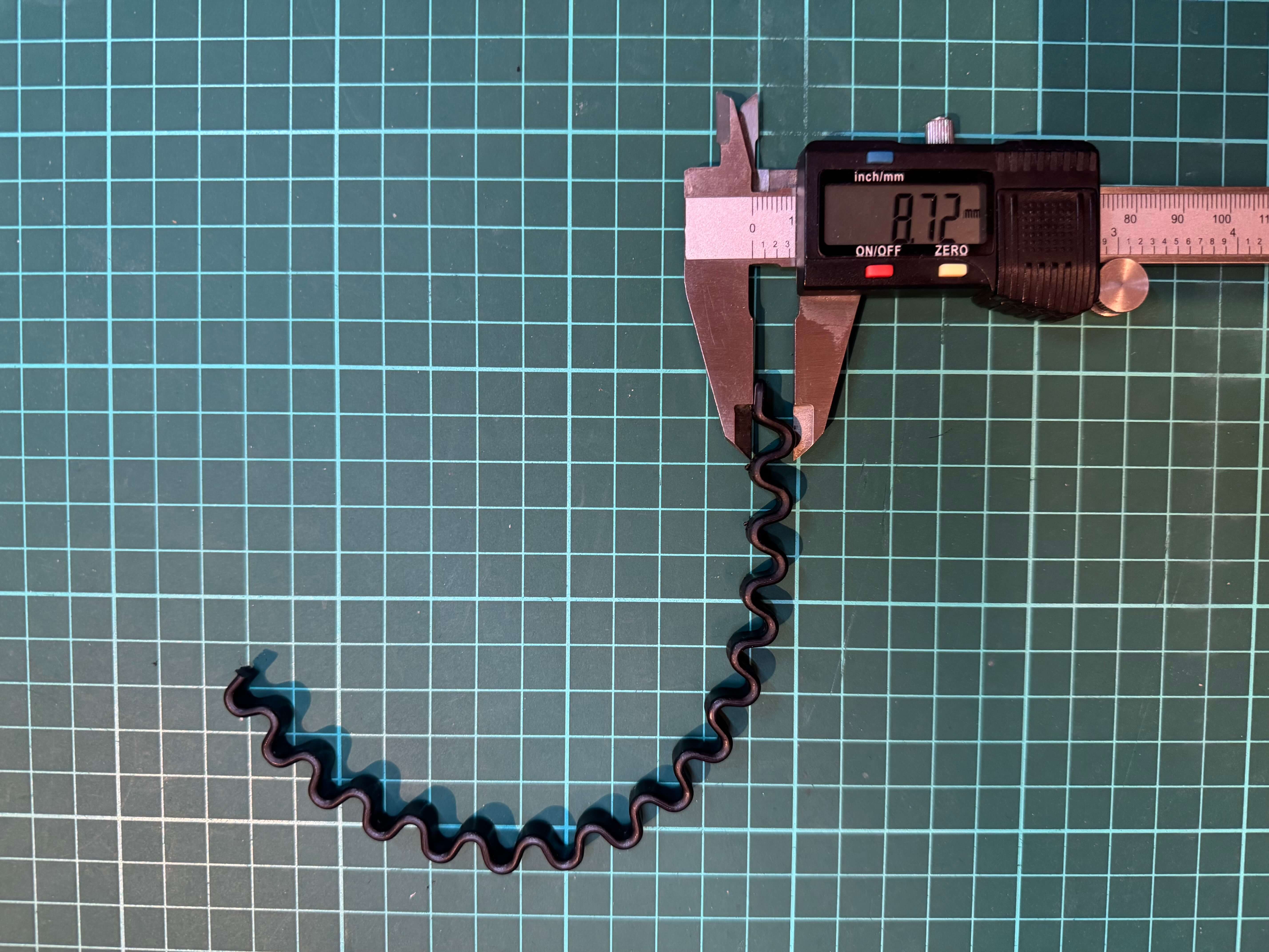
For my 3D modelling task I decided to go with something that would help me learn CAD a little more but also will be of use to me. I chose to model a headband of my girl friend's as it broke and she needed a new one. So I decided to make a 3D digital model of it so I could 3D print a replacement one for her. It had a very particular shape and repeating pattern to it but I figured that with enough measurements, I would be able to make a 3D model of it.
Working in Fusion 360
- Measure the headband
- Sketch out the general shape via fit point spline
- Sketch out the repeating pattern into the same sketch
- Create a plane for the cross section of the band
- Sketch out the cross section
- Extrude the sketch along the line from the repeating pattern topdown
- Repeat the pattern along the band
- Combine everything into one body
- Inspect what went a little wrong
- Search forums of F360


Results
After a few hours of work, I had a 3D model of the headband. I still need to add some polish to it, but I am happy with the result. I will 3D print it and see if it fits my girl friend's head. I am excited to see how it will turn out.
Cutting Plotter
Sticker design
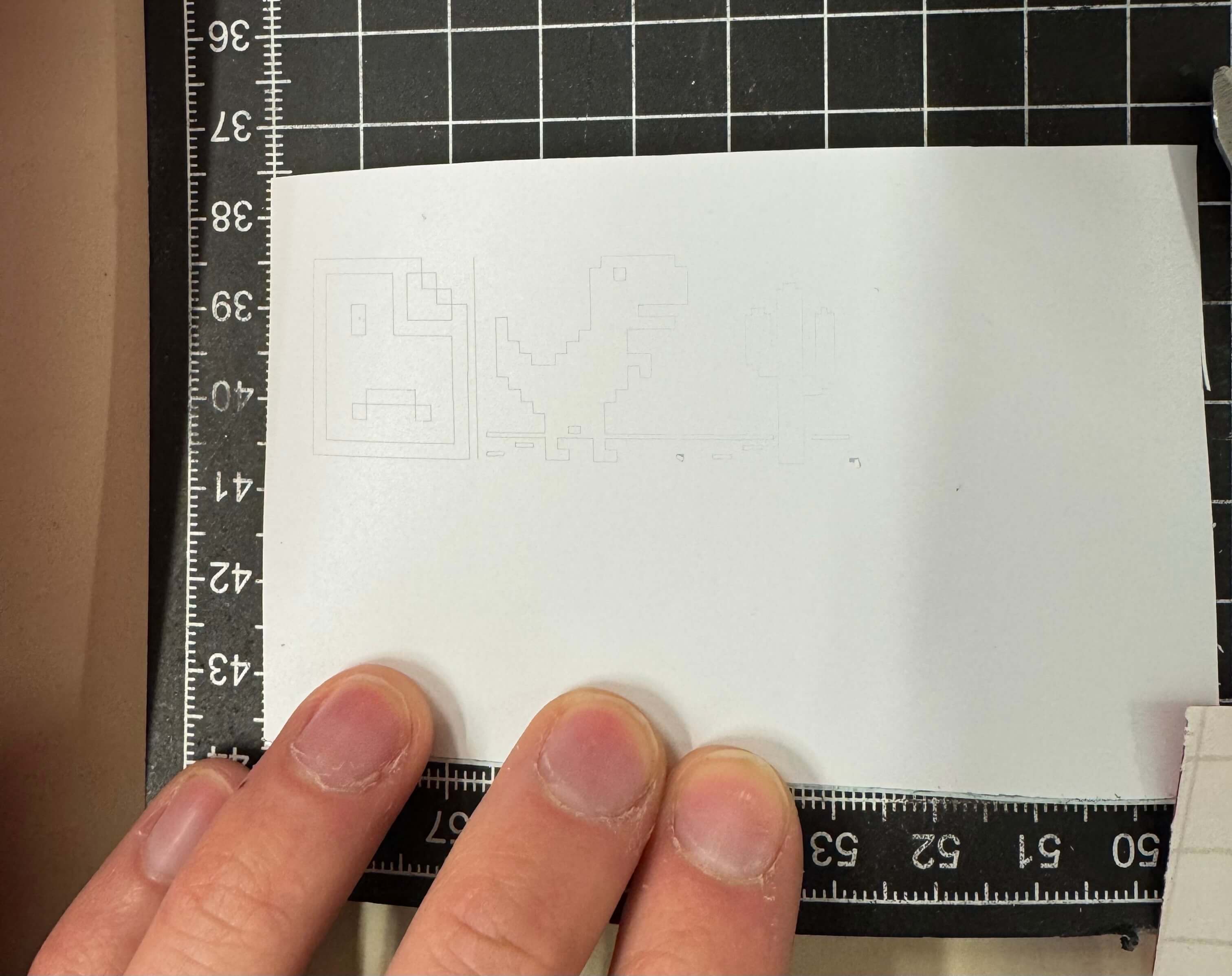
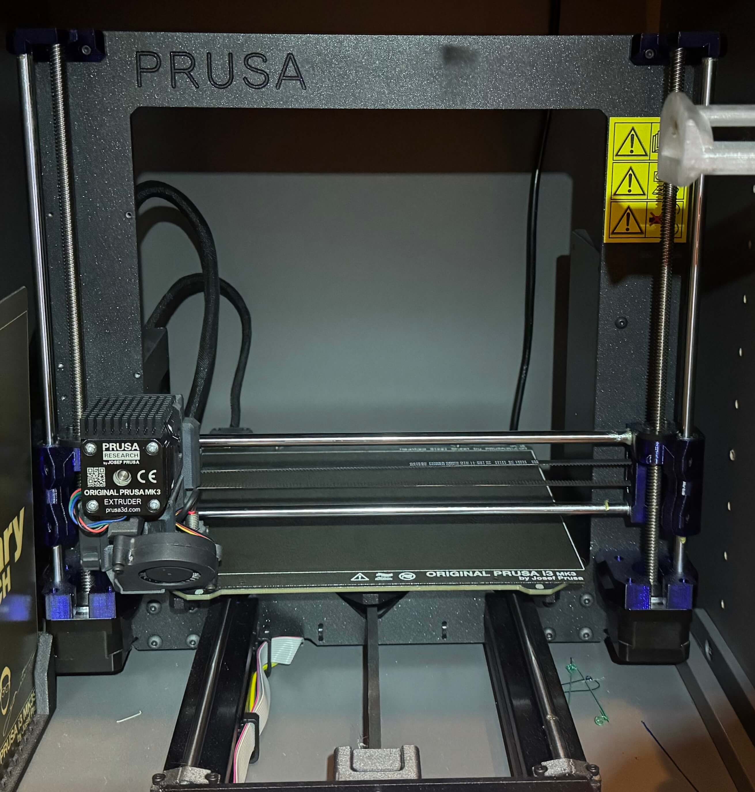
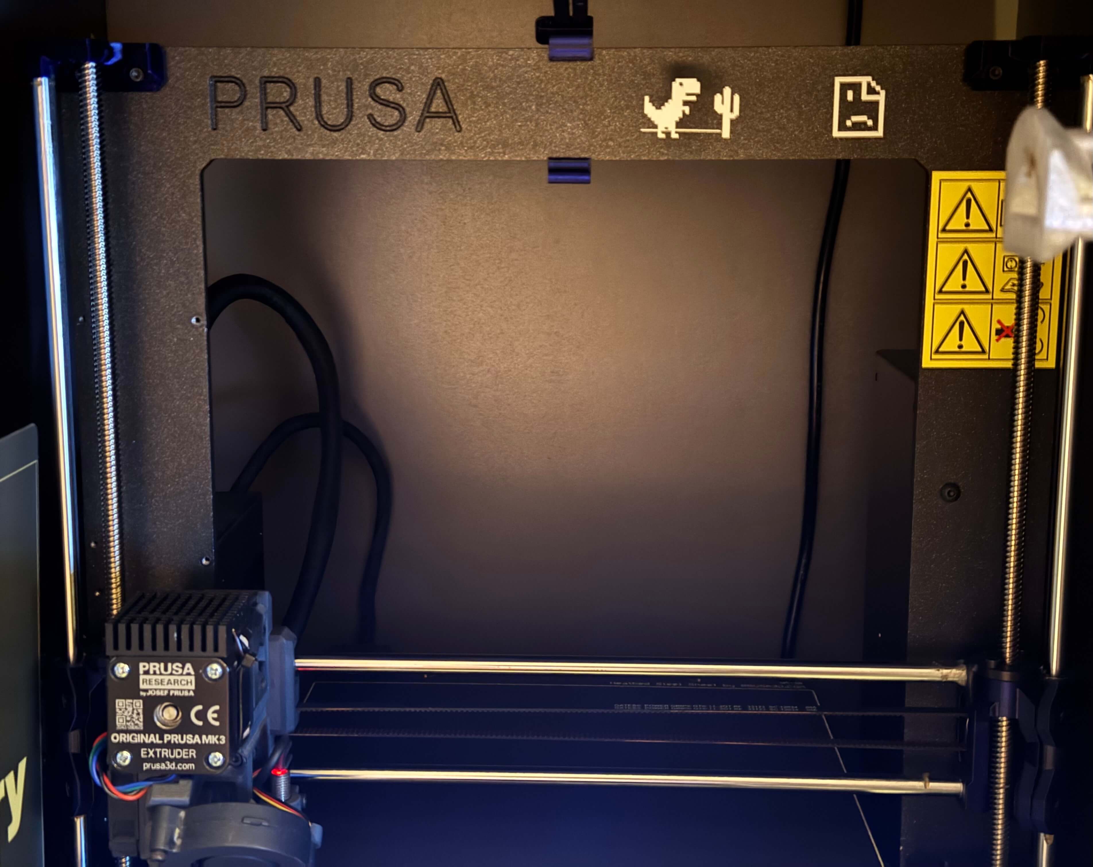
I decided to cut out stickers that I wanted to put on one of my printers. I bought it as a decommissioned farm printer from the Prusa Manufacturing print farm. Back there, it went by its identification number and accompanying bar code reading 404. It also had “Err” written on the top of its frame beside the Prusa text. I took it apart and put it back together with new printed parts and replacement bearings and named her ERRika. I figured it would be cute if I added some stickers reminiscent of the “error” aesthetic she carries. I found a “page not found” icon and the Dino from the Google browser game that you can play when you don't have an internet connection.

Preparation for cutting
- Download both the images from the web
- In Inkscape converted them from JPEG/PNG to vector graphics via the XXX tool.
- Export them in SVG form
- In Fusion 360, create a sketch with an outline of the dimensions of the printers frame - the place where I wanted to put the sticker
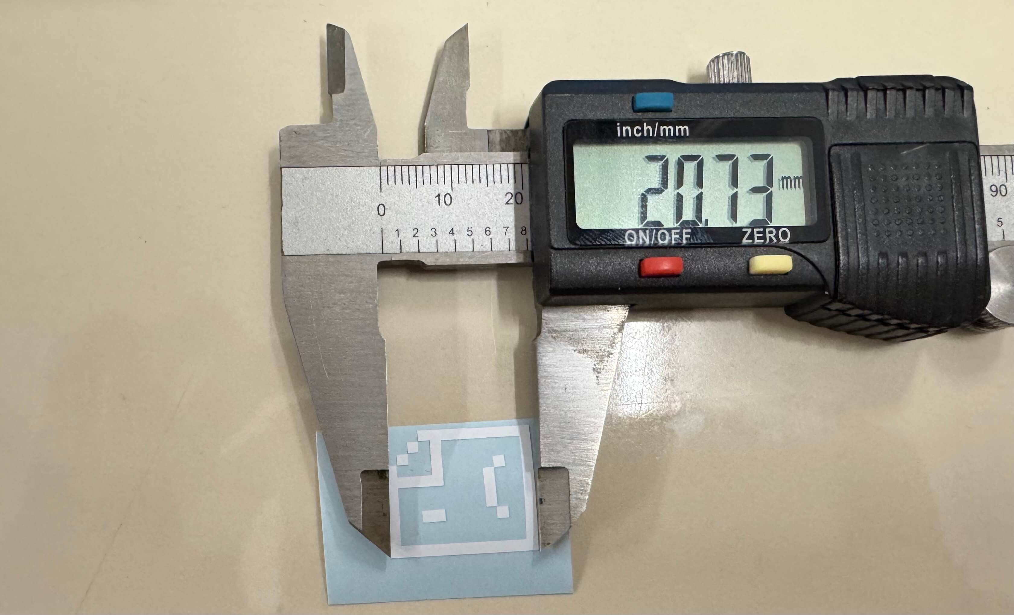
- Insert the SVGs from Inkscape and sized them to be about the same size as the “Prusa” text on the left side of the frame ~=~ 20mm in height.
- Export the sketch from Fusion 360 in DXF format

Cutting
- Put the DXF on a flash drive
- Open file on the computer connected to the cutting plotter - in my case, it was a Silhouette machine, which uses Silhouette Studio.
- Prepare the vector graphic for cutting
- Delete any unwanted lines (in my case the construction lines from F360)
- Scale the graphic to the wanted dimensions of the physical sticker
- Prepare a piece of sticker foil that has some margin (5-10mm) over the size of the sticker you want to cut
- Stick it on the cutting plotters transparent sheet. Be careful to match the the placement of the sticker paper to the placement of the sticker in the program.
- Load the mat into the plotting cutter
- Double check everything is ready
- Let the plotter cut
- Make sure the blade is set to the right depth - I set the depth to "2" as I had very delicate sticker pieces
- Make sure the right material is selected in the software - I had "Matte Vinyl" (dont remember for sure the complete correct name) pre-set for me.
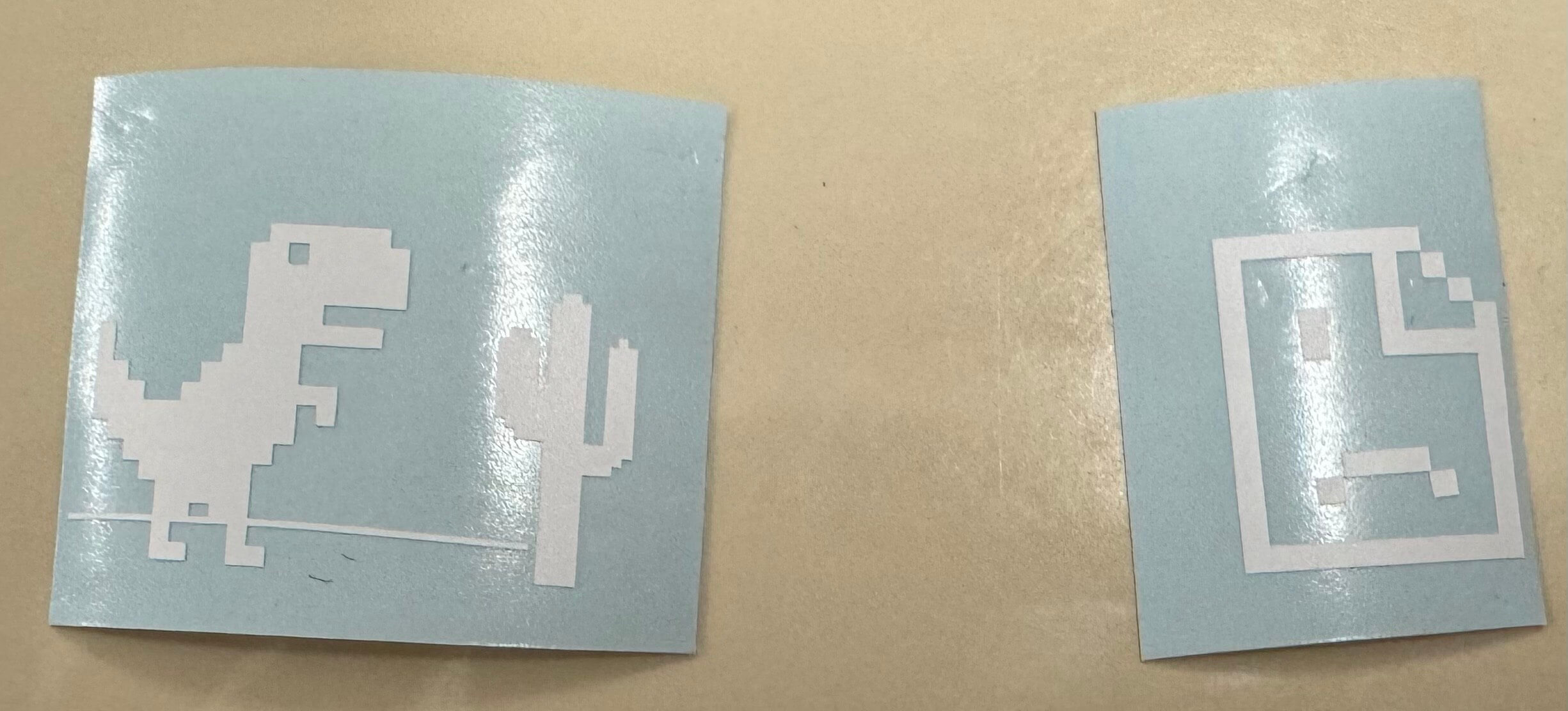
- Take out your sticker paper from the cutting mat
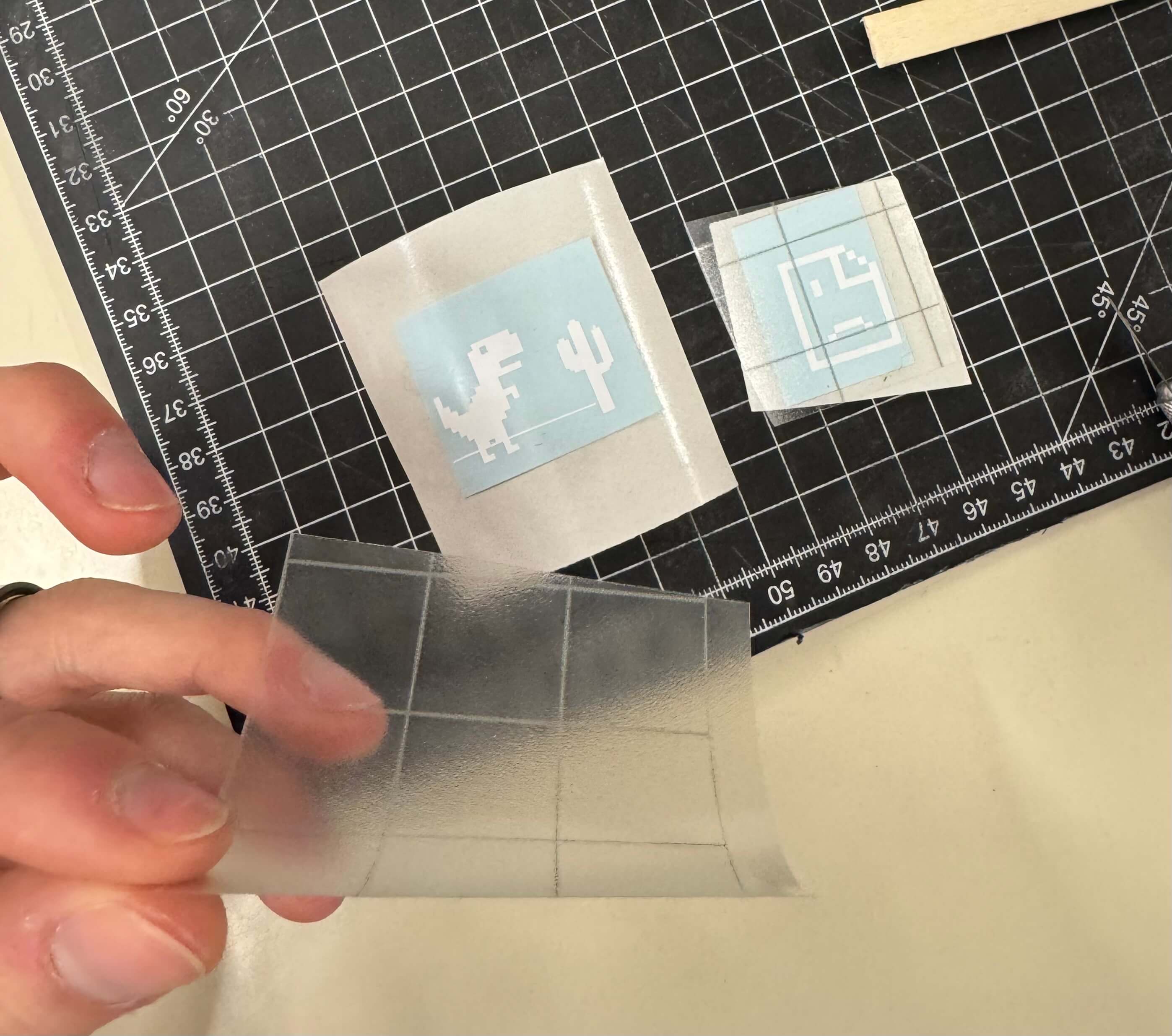
Post processing
- Remove the unwanted parts from the sticker via a pick or an exacto knife
- Cut a piece of transfer foil, prefferably at least a little bigger than the sticker, and carefully apply it to the sticker
- Package the sticker for later use (put the transfer foil carrier under the whole sticker to avoid the transfer foil sticking to anything unwanted)
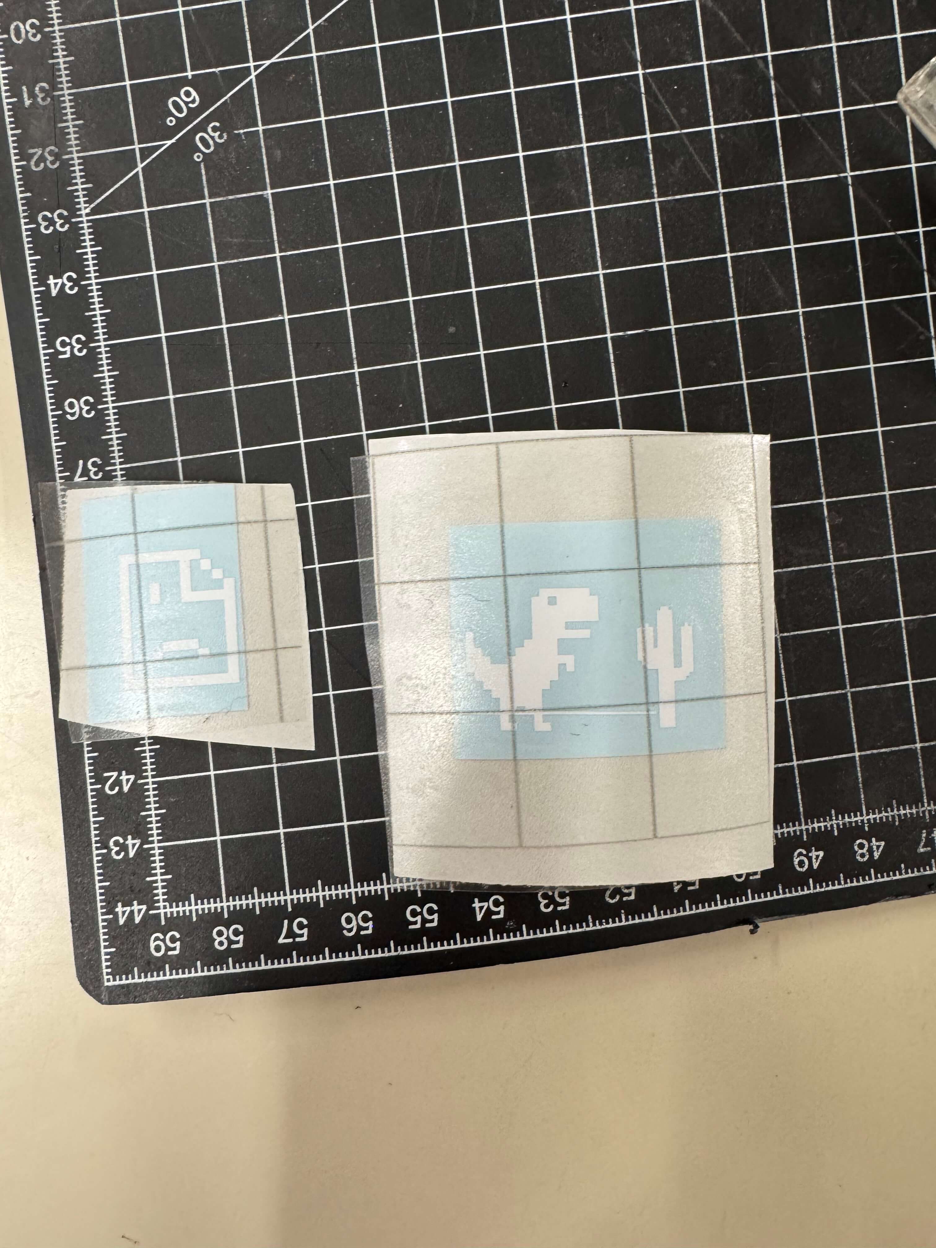
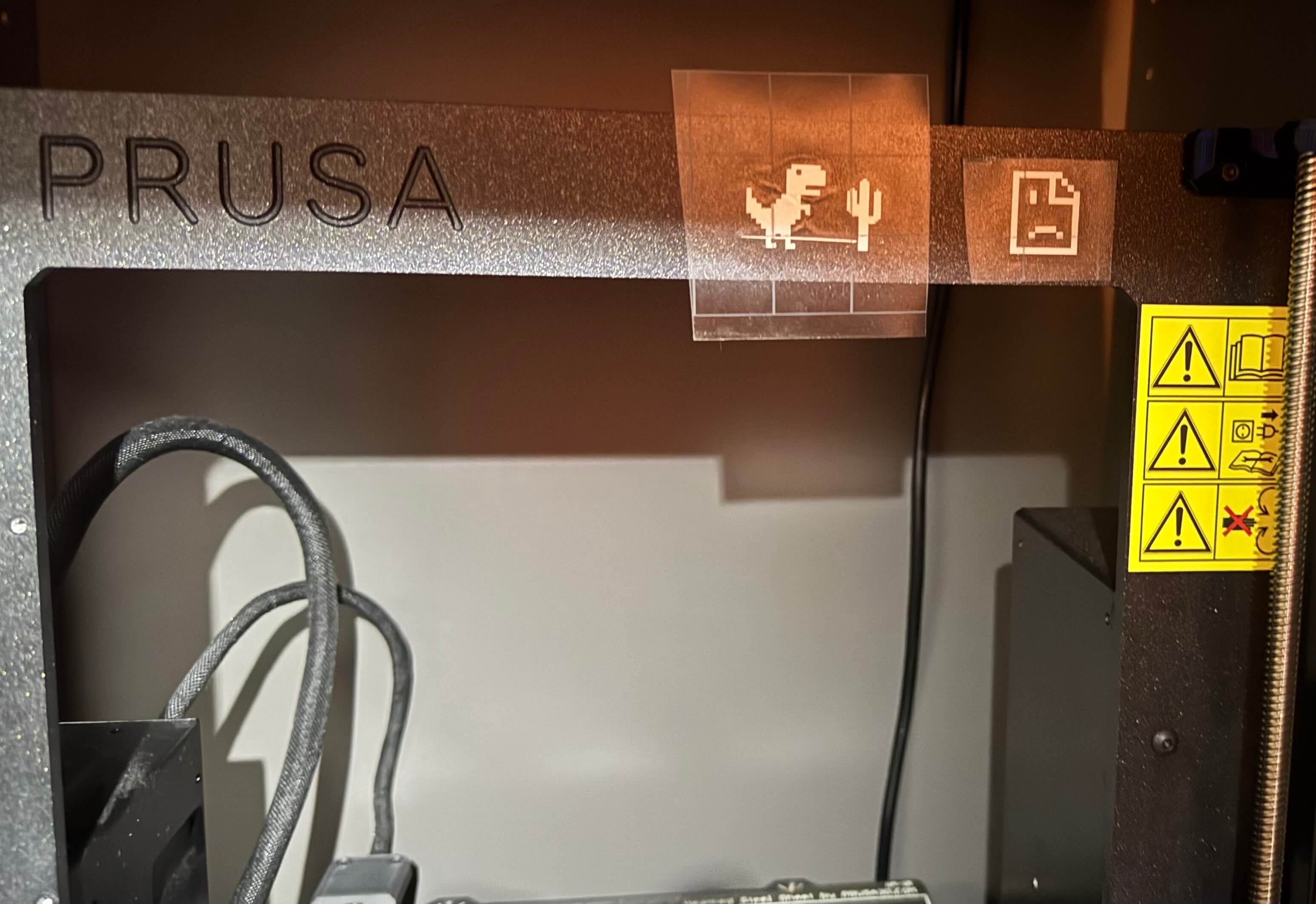
Results
After cutting the stickers, I was very happy with the result. The stickers looked great and I was excited to put them on the printer. I put them on the frame of the printer and they looked great. I was very happy with the result and am excited to show them to anyone who comes to my place.
*I would like to mention here that the name of my printer has NO association with a certain German chant.
Laser
Designing a puzzle in Fusion 360
- Create a new sketch/li>
- Define user parameters of the cardboard width (for the pieces to slot into) and then the gap length (how long the slot for the cardboard pieces should be).
- Draw basic geometric shapes and put rectangles with gap dimensions intersecting with their sides. Those will be cut out as holes for the other pieces to slot into.
I drew circles of two different diameters - 40 & 50 mm, triangles, and also experimented with the “slot” shape.
When I had one of the shapes done, I copy-pasted them from 4-8 times so that I could have more pieces of the same shape. Then again exported the sketch in DXF format.


Test run
I put the files on a flash drive and brought them to the laser cutter. Opened the DXF file in Adobe Illustrator. I wanted to figure out the correct dimensions for the interlock gap, so I deleted most of the pieces and cut out just three, not to waste precious cardboard. We fiddled around with the setup a little, but almost everything (focus, speed, frequency, power) was set up for us by the previous group. The settings used for the Epilog Mini 18 40W were:
- Speed: 100%
- Power: 30%
- Frequency: 500Hz
Then we did a test run with the laser cutter with the lid open so only the indicator light showing where the laser would cut was on. After repositioning a bit, we ran it again, checked that the laser will cut into a blank piece of cardboard. Then we ran the actual cutting job. NEVER FORGET TO TURN ON THE EXHAUST/FILTRATION SYSTEM AND THE AIR COMPRESSOR BEFORE CUTTING! And also leave it on for a few secs after the job is done. I tried fitting the pieces together - and with the feedback of Jakub Fink got to revising my model.
That's where I ran into multiple issues:
- Duplicate lines stacked on top of each other. This means the laser would run/cut through the same line multiple times, which is especially bad for the quality of the cut, resulting in charred edges and generally unclean cuts.
- The construction lines that are easily told apart in Fusion with dashed lines were converted to the same one type of line in the Adobe Illustrator program used with the cutter.
Pro Tip
Do NOT use construction lines in your sketches as they are NOT recognized as different in the exported DXF. They cannot be selected and deleted at once. If you need to use them for some constraints but do not want to cut them, you should: CREATE A NEW SKETCH in the same plane and PROJECT only the final lines/shapes you want to be cut into it.I was not expecting the revision of the DXF file to take so long. When I finally had it, I ran into the last issue: My flash disk was later found out to be faulty, as it either didn’t show up at all, showed up as some kind of CD-ROM device, or showed up but the DXF file on it got corrupted somehow.
Results
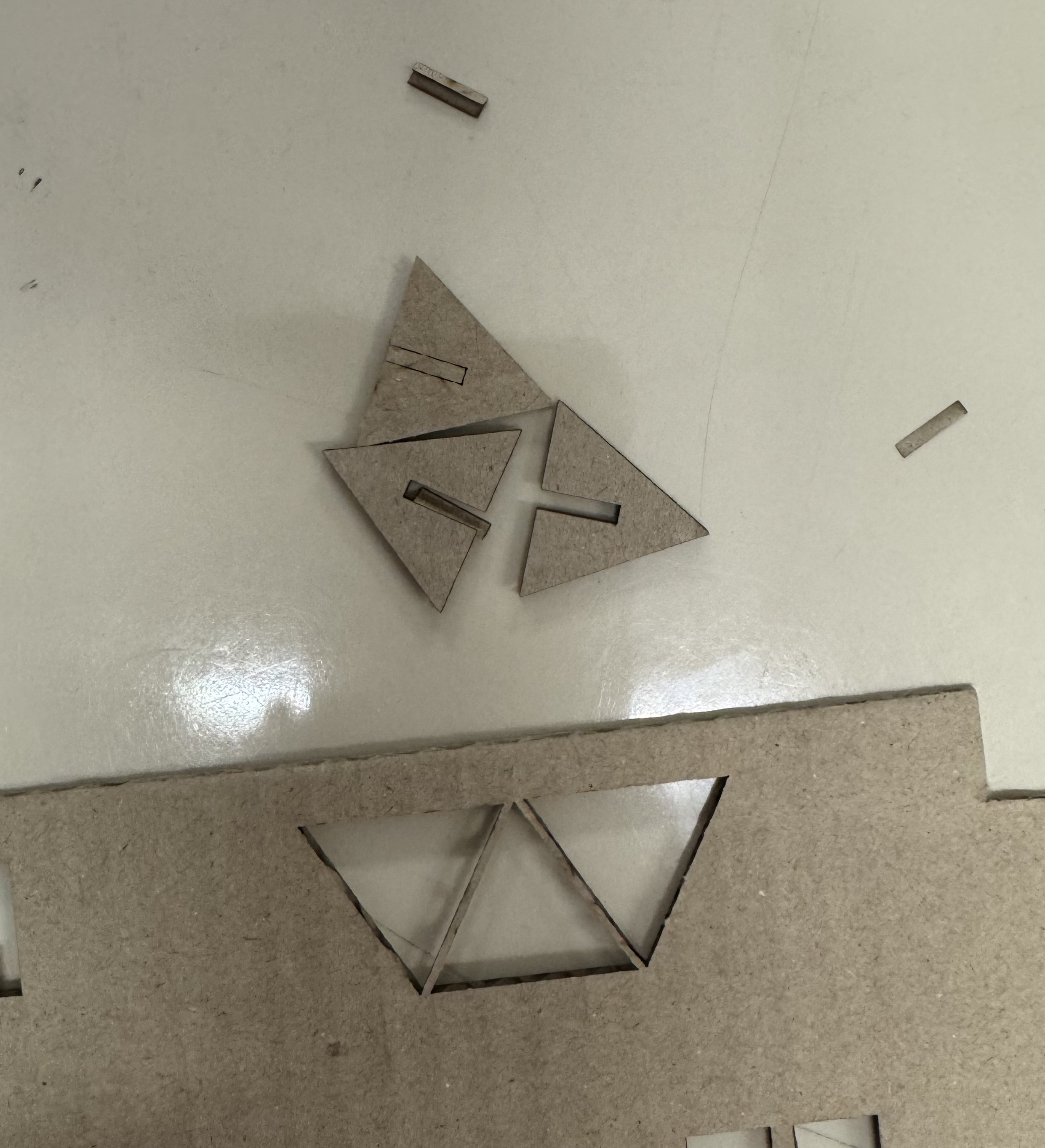
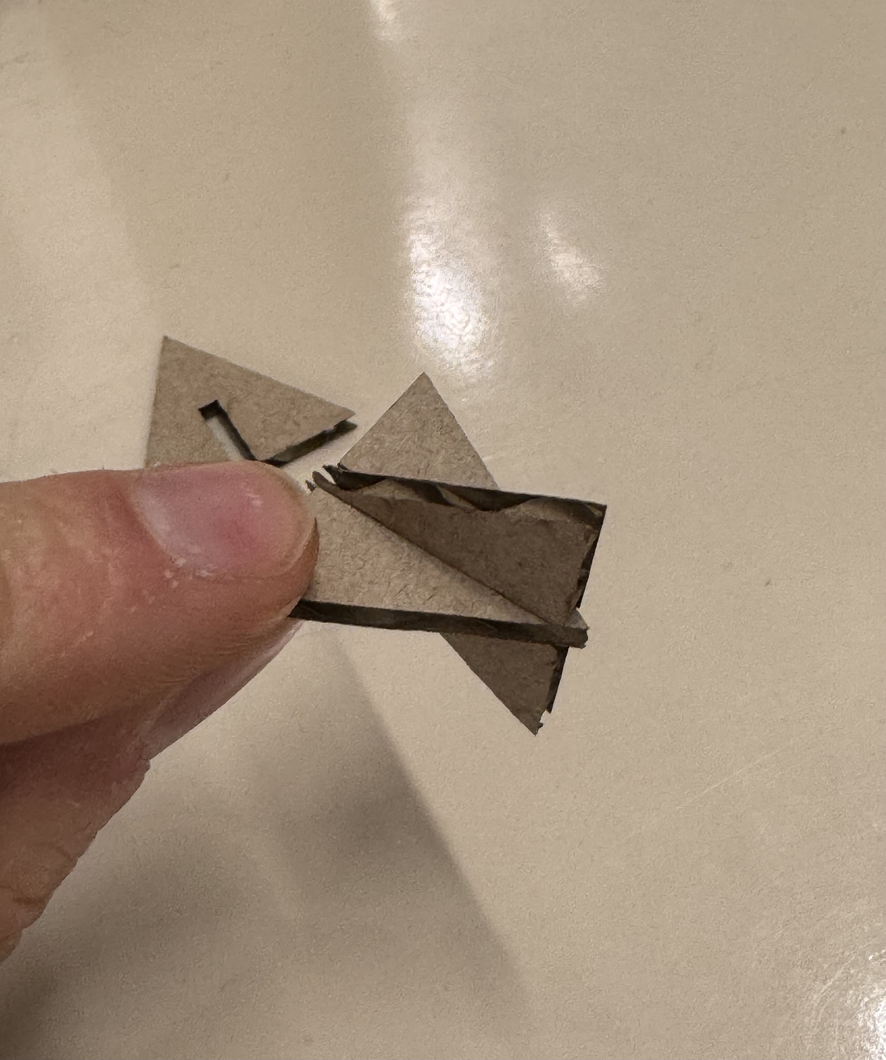
Technically, my pieces that I managed to actually cut were not flat. They stuck perfectly together and created this sort of “lattice” shape. So that is what i'll be bringing to the show and tell. Because of the time-consuming issues I ran into. A good proof of concept tho. I am looking forward to using this fabrication technique in my future projects and with stronger materials and better preparation on my part.
Key Takeaways
- Do everything you can do at home at home, dont leave it for the lab. Time is limited and if you run into issues, you better fix them fast.
- Always double-check your files before you go to the cutter
- Be careful with construction lines, see also the laser section's Pro Tip
- Always have a backup of your files
- Don't be afraid to ask for help
- Take more pictures